
Perfect consistency on every joint of a circuit board challenges even advanced production lines. A small fluctuation in process conditions is enough to form a cold solder joint. The defect often slips past initial visual checks undetected. Intermittent field failures then surface long after the product leaves the factory.
A single bad connection can jeopardize an entire production run. Knowing where the process breaks down is essential to protecting factory yield. The causes fall into a handful of physical triggers, each one preventable. Understanding those triggers is the first move toward eliminating them.
Understanding What Causes a Cold Solder Joint
A cold solder joint forms when the alloy never reaches full melting temperature or cools too soon. The metallurgical bond fails to develop, leaving a weak or detached connection. The failure traces back to a few specific anomalies on the floor. Each one is recognizable once an engineer knows the signature.
Several factors lead to a cold solder joint during assembly, and most relate to heat or cleanliness.
- Inadequate heat delivery – Too little energy melts the alloy only partially, so the bond never completes. Robotic systems counter this by applying a customized thermal profile for each.
- Insufficient flux – Missing or burned-off flux leaves the oxidation layer intact, so the molten alloy cannot wet the pad.
- Premature cooling – Pulling heat too early, or a localized draft, freezes the alloy before it flows across the connection.
- Component movement – Vibration or shifting during solidification disrupts the bond and seeds internal micro-fractures.
- Contaminated surfaces – Oxidation, grease, or residue blocks adhesion, so the alloy beads up rather than wetting the pad.
Heat delivery deserves particular attention, since the board itself often steals the energy. Dense assemblies and heavy copper planes pull warmth away from the joint laterally. The design guide notes a common misconception worth correcting here. More power does not heat the joint faster, because the contact patch limits how quickly heat moves into the board. Recognizing these triggers lets a team adjust parameters for cleaner runs.
The Hidden Risks of a Cold Solder Joint
A cold solder joint poses a hidden threat to the long-term performance of a board. The metal often keeps mechanical contact, so the flaw passes electrical and optical inspection. The defect, therefore, stays unnoticed until the assembly reaches the field. A connection that looks acceptable can still fail under real conditions.
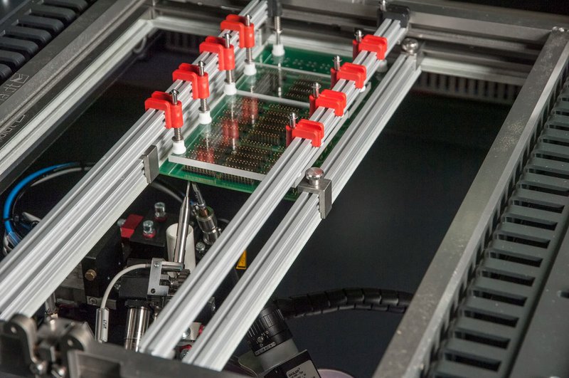
Leaving these flaws in place introduces several costly risks to a facility.
- Intermittent failures – Micro-fractures expand and contract with temperature, creating erratic electrical paths and unpredictable malfunctions.
- Field recalls – A board that escapes testing eventually fails under vibration, which carries heavy cost and liability in medical or automotive systems.
- Rework expense – Pinpointing one structural failure on a dense board consumes diagnostic time and inflates scrap rates.
- Accelerated degradation – A brittle, poorly bonded alloy fatigues over time until normal handling or thermal stress breaks it entirely.
Inspection alone cannot be trusted to catch the defect, which is what makes it dangerous. A joint with mechanical contact but no proper bond reads as good to most automated checks. The safer path is preventing the flaw at the source rather than hunting it afterward. High-precision soldering heads lock in the parameters that keep weak joints from forming at all.
Designing Out the Cold Solder Joint Through Thermal Balance
Floor adjustments resolve immediate heating issues, yet real prevention starts at layout. A poorly designed board creates thermal sinks that drain energy from the target area. The drain makes a proper metallurgical bond difficult to achieve regardless of the tool. A balanced layout removes the physical conditions that trigger a cold solder joint.

A few board-design choices ease heat delivery for any soldering process.
- Thermal relief pads – A pad tied directly to a large ground plane behaves like a heat sink. Thermal relief spokes restrict that dissipation so the local zone reaches bonding temperature.
- Sensible pad dimensions – Mismatched pad sizes draw heat unevenly across leads, so the alloy solidifies unevenly. Pads sized for the larger joint, or D-shaped pads, help balance the draw.
- Uniform copper distribution – Concentrating heavy copper on one section causes localized temperature drops. Distributing the planes evens out the thermal variation that disrupts wetting.
One caution belongs with the thermal relief advice. The spokes of a relief must still carry the current that the design expects to pass through them. Board designers own that tradeoff, since they hold the electrical requirements. Working through it together with the soldering process owner, the right balance is reached.
Some joints carry so much thermal mass that layout alone cannot solve them. The design guide offers a direct remedy for those cases. Two irons applied at once double the contact patch and push heat in faster than the board pulls it away. High-mass joints repay early testing, so the pad and the budget can account for a second iron.
Secure Yield and Reliability in Your Soldering Process
Preventing a cold solder joint means removing process variables and building a thermally balanced board early. The two efforts reinforce each other across the production run. A stable thermal profile finishes the work that good layout begins. Yield and field reliability both rise as the defect rate falls.
The right approach depends on the board, the joint, and the production target, which a drawing alone rarely settles. mta robotics locks in these parameters with high-precision soldering heads and integrated robots, backed by laboratory testing on real prototypes. The team evaluates drawings and tests parts before any commitment is made. Kontaktieren Sie das Team von mta robotics to the mta robotics team to validate your boards and secure a process guarantee for your line.